Proel AMP03 User Manual
Browse online or download User Manual for Receivers and Amplifiers Proel AMP03. Proel AMP03 User Manual
- Page / 15
- Table of contents
- BOOKMARKS
Summary of Contents
INSTRUCTION MANUAL PA Mixing Amplifier AMP03
• Speakers power sum should not be lower than the amplifier output power. • We suggest you to don’t use long cables. Anyhow, for longer distances
CONSTANT VOLTAGE LINE. If you’re using a constant voltage line, connect either the 100V to the “+” side of speaker system, and connect COM to “-“ s
6. OPERATIONS: a. Pressing the POWER switch the unit turns on, and its LED is lit. Pressing it again the unit turns off. b. BASS (150Hz) control
7. Technical specifications Model AMP03 Output RMS / MAX power 30 W / 60 W Constant voltage output 100V Constant impedance
The product is in compliance with Directive 89/336/EEC (Electromagnetic Compatibility) and following modifications 92/31
PROEL S.p.A. (World Headquarters - Factory) Via alla Ruenia 37/43 64027 Sant’Omero (Te) – Italy Tel: +3
1. IMPORTANT SAFETY INSTRUCTIONS CAUTION: To reduce the risk of electric shock
Sentences preceded by symbol contain important safety instruction. Please read it carefully. DETAILED SAFETY INSTRUCTIONS. Water and moisture:
Objects or liquid entry inside the unit: Be careful that no objects fall or liquid is spilled inside the unit through ventilation openings. Safe
• To obtain good speakers wire contacts, please tighten the screw terminals firmly. • For safety reason, don’t defeat the grounding connection. Gr
Thank you for choosing one of Proel products, and for your confidence towards our brand, synonymous of professionalism, accuracy, high quality and re
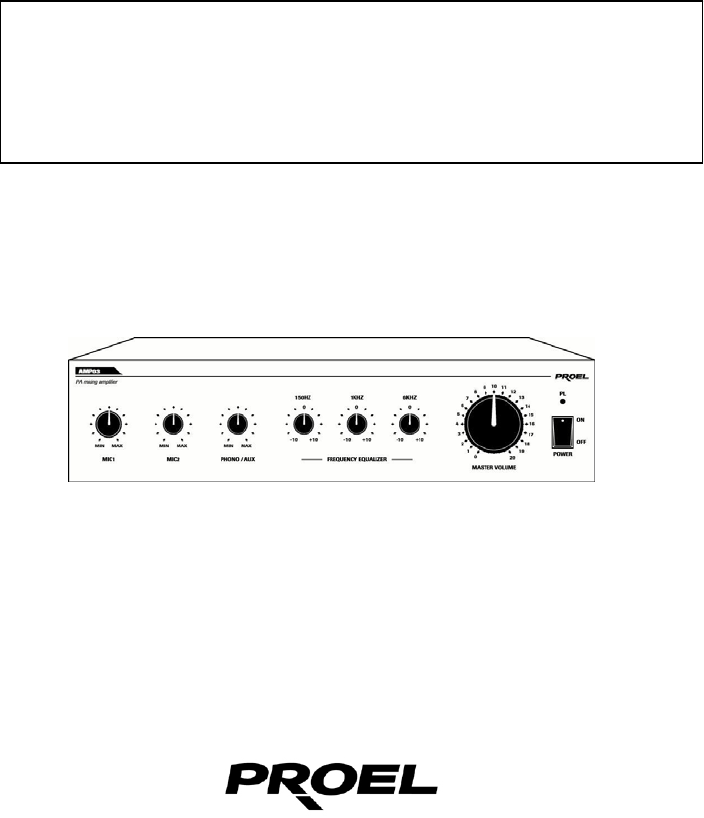
2. FRONT PANEL DESCRIPTION fig.1 1) Power On/Off switch. 2) MASTER output volume control. 3) High frequency tone control (6 KHz). 4) Middle
8) PHONO input (RCA connectors). 9) AUX/CD input (RCA connectors). 10) Grounding terminal. 5. INSTALLATION 1. Input connections • MICROPHO
• AUX /PHONE CD players, cassette decks, tuners, mixers and other external line level output equipment may be connected to AUX input. The sele
More documents for Receivers and Amplifiers PROEL AMP03

Related products and manuals for Receivers and Amplifiers Proel AMP03
 (13 pages)


 (47 pages)
© 2020, manymanuals.com. All rights reserved. | 0.723 s |
 Manymanuals.com
 Manymanuals.de
 Manymanuals.fr
 Manymanuals.it
 Manymanuals.pl
 Manymanuals.cz
 Manymanuals.es
 Manymanuals-pt.com
Comments to this Manuals